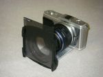
One of the joys of mirrorless interchangeable lens cameras is the ability to experiment with older lenses, bellows, and similar equipment without any tedious record keeping or expense of film. With a simple attachment, one can readily adapt a mirrorless camera to experiment with one of the earliest photographic techniques, using a pinhole rather than a lens to project the image.

MkII pinhole non-lens on E-P1
Supplies needed:
C-mount to Micro Four Thirds lens adapter (~$10 off eBay)
Large metal washer to fit the recess in the C-mount adapter (~$1 at local hardware store)
Aluminum flashing or similar thin sheet (also at hardware store, or from the peel-off top of a food container (bread crumbs, soft cat food, etc.) )
CA adhesive (“Superglue”)
PVA adhesive (“Elmer’s Glue-All”)
Marking tool (pencil or ultra-fine point Sharpie brand marker)
Scissors (capable of cutting the aluminum)
Center punch, hardwood block, and small hammer
600 grit wet-or-dry sandpaper and flat surface (glass sheet, marble block, etc.)
Needle and softwood block
Ruler marked in millimeters (for the obsessive)
Flat black spray paint (optional)

Parts for first prototype.
1. Use the inner edge of the washer to trace circles onto the aluminum sheet. Then, use the C-mount adapter to trace a larger circles around the smaller circles; these circles should be spaced in slightly from the inner edge of the opening in the C-mount adapter. Cut out the circles. Note that the metal edges may be sharp enough to cut through skin!
2. Use the punch to make an indent in the center of each cut-out circle. This should only take a very light tap. (Note that the photo shows punching disks for the second prototype, in which the dimples are punches first and then the disk cut out around the indent.)

3. Sand the side of the aluminum circle with the bulge on a flat surface (the photo shows a marble block salvaged from a bowling trophy – $0.50 at a yard sale years ago) until the bulge has been flattened. (Again, the photo shows disks for the second prototype – cutting the parts crudely (very crudely) to shape and selecting the most promising disk or two before cutting the circle saves effort in cutting.)


4. Use the needle to poke a small hole in the center of each indent to form aperture disks. Ideally, the hole should be 0.2mm in diameter for a Four Thirds sized sensor. Since the ruler likely is not marked finer than millimeters, estimate about 1/5. The first try, most likely the smallest hole will still be overly large.

No, I don’t really believe that readers really need this step illustrated.
Yes, I should have trimmed my nails.

5. Select the best-looking of the punched disks and use CA adhesive to attach it onto the washer, with the punched hole centered in the washer opening.
6. Optionally, spray the washer and disk (on the side of the washer onto which the disk is attached) flat black.
7. Position the washer in the recess in the C-mount adapter (with the aperture disk facing inwards toward the camera-mounting side) and move it until the aperture is centered. Use dots of PVA glue around the washer (applied on the outer lens-mounting side of the adapter) to attach the washer in position, and set aside to let the glue cure.

Testing of the Mark I suggested that the aperture was too large, resulting in a blurry image.

The optimal pinhole size calculator at:
http://www.mrpinhole.com/wiz.php?Func=FilmDimension
indicates that, for a Four Thirds sensor (17mm x 13mm), the optimal size would be 0.2mm. Comparing the aperture to a ruler revealed in an estimated 0.4 mm aperture, rather than the optimal 0.2 mm.
Naively believing that a sharper image could be attained with the proper aperture size, the MkI device was modified.

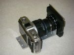
To provide a smaller aperture, and the ability to readily change the aperture disk as needed, the aperture of the Mark I device was drilled out a bit and a new aperture disk added to form the Mark II device. The new aperture disk is cut smaller than the washer opening and is attached atop old Mark I aperture disk using PVA glue in the same manner as the washer was attached to the C-mount adapter.

The aperture can be readily centered by holding the assembly overhead and holding the disk down while applying the glue; just be sure that the neighbors aren’t watching this spectacle. The glue allows the new disk to be readily removed for replacement, which facilitates trying different aperture sizes.
Attaching the washer to the C-mount adapter by PVA glue allows it to be removed if it is desired to use the C-mount adapter for its intended purpose, such as after finding that the image is blurry no matter what size aperture is used, due to the diffraction of light.

MkII with estimated 0.25mm aperture

MkII with estimated 0.2mm aperture